
Table of Contents
Filter circuits:
The output obtained from a junction diode rectifier is unidirectional but pulsating. Such a signal can be considered as the sum of a d.c. signal superimposed with many a.c. signals of different harmonic frequencies. We can obtain d.c. voltage by filtering out the a.c. components. We describe here two simplest filter circuits.
1. Series inductor filter:
Figure shows the circuit of a full wave rectifier with an inductor of inductance L connected in series with its load resistance RL.

The inductance L offers a reactance XL =2πfL to the flow of current through it. Clearly, it blocks high frequency a.c. component and allows low frequency d.c. component to pass through it. A smooth d.c. voltage appears across the load resistance.
2. Shunt capacitor filter:
Figure shows the circuit of a full wave rectifier with a capacitor of capacitance C connected in parallel with its load resistance RL.
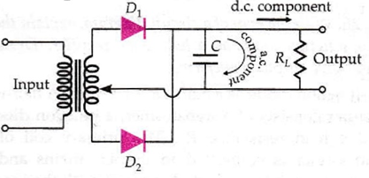
The capacitor has a reactance of high capacitance C offers a low impedance path to high frequency a.c. component but high, almost infinite, impedance to low frequency d.c. component. Hence the a.c. component is bypassed through C or filtered. A smooth d.c. voltage appears at the load resistance.