
Table of Contents
Junction diode as a half-wave rectifier:
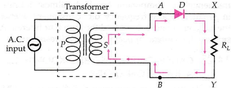
A half-wave rectifier consists of a transformer, a junction diode D and a load resistance RL. Tire primary coil of the transformer is connected to the a.c. mains and the secondary coil is connected in series with the junction diode D and load resistance RL. We assume that the diode is ideal so that it offers infinite resistance during the reverse biasing.
Working:
When a.c. is supplied to the primary, the secondary of the transformer supplies desired alternating voltage across A and B. During the positive half cycle of a.c., the end A is positive and the end B is negative. The diode Dis forward biased and a current l flows through RL. As the input voltage increases or decreases, the current l also increases or decreases and so does output voltage (=IRL) across the load RL. Output voltage across RL is of same waveform as the positive half wave of the input.

During the negative half cycle, the end A becomes negative and B positive. The diode is reverse biased and no current flows. No voltage appears across RL. In the next positive half cycle, again we get output voltage. The output voltage is unidirectional but pulsating, as shown in Fig. Since the voltage across the load appears only during the positive half cycle of the input a.c., this process is called half-wave rectification and the arrangement used is called a half-wave rectifier.